It was a time when dealing with fluctuated or inconsistent power supply was a cumbersome task. To handle this Voltage stabilizers are being used from the early days of technological evolution. In conventional or old modeled voltage stabilizer one mechanical rotary was being used with an autotransformer to control the output voltage of mains power. As time changes, many of the manufacturers changed their voltage stabilizer design to provide a more efficient and stable supply. In those several designs Microcontroller based voltage stabilizer is one of them. Several models are present in the market based on their load handling capacity. Here we are mainly focused on the voltage stabilizer for home appliances. Let’s get into this to know more.
What is This?
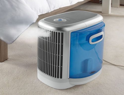
These stabilizers are also known as an automatic voltage stabilizers. A voltage stabilizer is a device that stabilizes the inconsistent AC power and keeps it between stable ranges (200 to 230 volts AC). Sometimes a variation of voltage or spikes appear on mains power (AC line), if we use this gadget then the variation can cause no problem to the appliances. It protects any electronic appliance like Air-Conditioner, Refrigerator, Washing machine, and much more.
In this gadget, microcontroller generates the control signals automatically by sensing this input power. Earlier versions of this gadget were using several timers and counter IC’s. These older versions are also performing automatic operations but their designs are not efficient. To solve this problem preprogrammed microcontrollers are introduced in the technical industries.
Engineering Inside:
Based on its load handling capacity its internal circuit units are changing. But few of them remain in every design and those are given below:
- Transformer
- Relays
- Control board
- MCBs
- LED display

Internal units of automatic voltage stabilizer
Transformer:
We know that transformer works based on mutual induction. In voltage stabilizer step down transformer is being used that works in two modes. The first one is Buck or step-down mode when mains or input AC power is higher than the defined value. And the second one is Boost or strep-up mode when mains power is lower than the desired value.
Buck mode:
In this mode, the secondary winding of the transformer is connected in such a way that secondary output voltage is deducted from incoming AC voltage. In case of a rise in mains power, the electronic circuit in the stabilizer switches the relay that switches deducted output voltage.
Boost mode:
In this configuration mode, the mains voltage is given to the transformer and this voltage is normally stepped down. The secondary winding of the transformer is connected in such a way that the secondary output is added to the primary or mains supply voltage. In case of low mains power, the electronic circuit in the stabilizer switches the corresponding relay to boost the input supply.
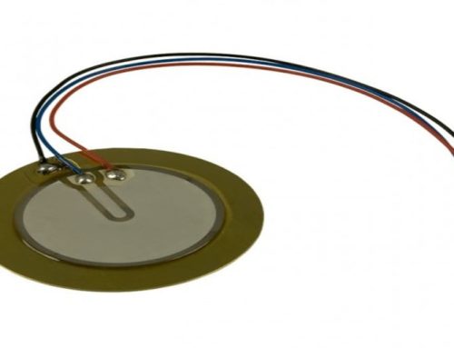
Relays:
Relay is a kind of electromechanical switch. The control board of the stabilizer unit compares the output voltage with a reference value provided by the built-in reference voltage. Whenever input power rises or falls, the control board switches the corresponding relay to connect a desired tapping to the output voltage.

Relay an electronic component
Control Board:
This unit is the brain of the microcontroller-based voltage stabilizer and its main function is to control the relays. By controlling the relays it changes the configuration of the transformer to work as either step-up or step-down mode. The control board contains a preprogrammed microcontroller, voltage regulator, counter IC’s, capacitors, and several electronic components. Its circuit design varies based on load handling capacity.

Micro-controller based control board
MSB’s:
MCB’s (Miniature Circuit Breaker) in this gadget work as an additional circuit protector. Suppose, if a short circuit occurs in the internal circuit or at the output then MCB’s protect against this. It automatically switches OFF the electrical circuit during the abnormal condition in the electrical network.
Working Process:
We have seen that an automatic voltage stabilizer at least contains a step-down transformer, relays, control board, and MCB’s. When input power comes to the transformer primary winding and several relays then a microcontroller-based control board senses the input voltage. If the input voltage is greater than a predefined reference value range then the control board switches the corresponding relays. And this changes the configuration of the transformer to reduce the input voltage to referenced voltage range. In the second case if the input voltage is lower than the reference voltage range then the control board switches the relays to change the configuration mode of the transformer. As per result, this new mode boosted the input voltage to the reference voltage range. That’s how it works.
Applications:
Based on load handling capacity this gadget size varies. It has several applications as per their load, some of them are given below:
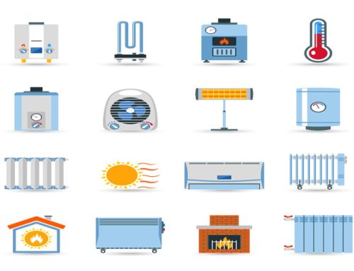
- In lighting equipment to protect it from abnormal voltages.
- To control the over-current in AC motors.
- Control voltage in induction heating.
- For several household equipment like Air-Conditioners, Refrigerators, and much more.
Thanks for reading. See you soon with another exploration!