Most of us had seen electric bulbs in childhood. As we are getting older technological enhancement improved our lighting system more effectively.
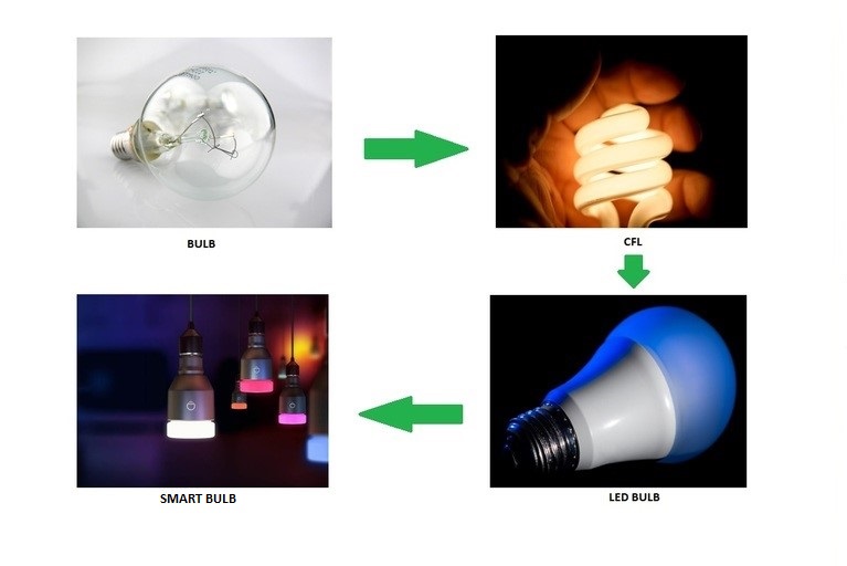
Up-gradation in lighting system
We have seen the journey of lightning up-gradation from simple electric bulb to CFL (Cathode Florence Tube), CFL to LED bulbs, LED bulbs to smart bulbs. This up-gradation stage is still moving on. Here we will explore the working of smart bulbs and their internal structure. So without any further delay let’s get started.
Wireless lighting control is gaining momentum with the growth of the IoT (Internet of Things). Smart lighting is the solution to make your smart house, office, retail and commercial spaces.
What are smart bulbs?
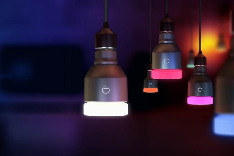
Smart bulbs
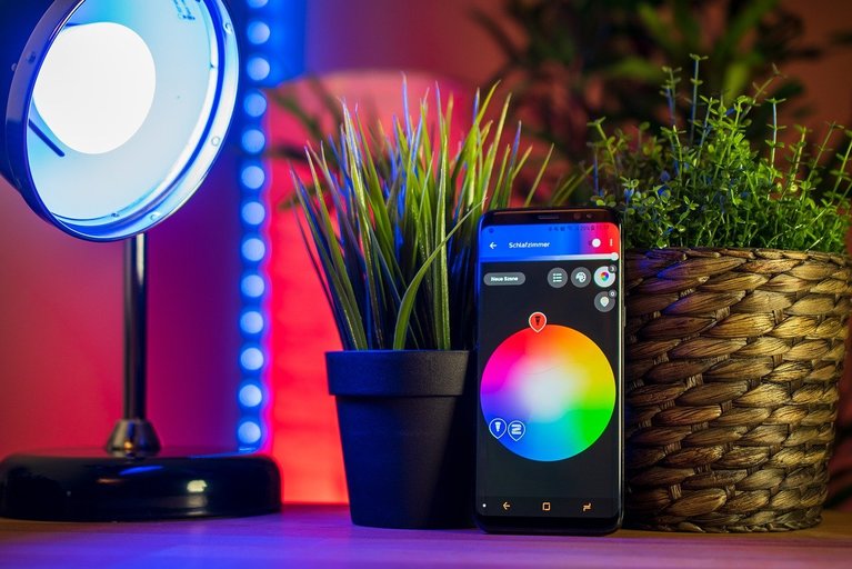
The smart bulb is an innovation that made peoples lazier. Oh sorry for this sarcastic comment. In simple word smart bulbs are providing a kind of lighting system which can be controlled remotely and wirelessly.
We can switch ON/OFF light bulbs, can change their colors, and also we can schedule its timing, and much more. Most of the smart bulbs are using LED’s to generate more efficient light.
How do smart bulbs perform this action? Which things make it possible? Now we are going to see the internal structure of smart bulbs. A smart bulb has mainly three parts:
- LED
- Wireless control circuit
- Power supply circuit
LED:
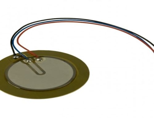
In any smart bulb, this unit is mainly responsible to generate light for the user. This unit contains various segmented or discrete LEDs to generate light of different colors with different intensities. We know that white light is a mixture of all colors of light and we can generate various colors by using three basics colors – RED, GREEN, and BLUE. In smart bulbs, each LED contains three different kinds of colored diodes. By using this segmented LED we can generate 16 million different colors.
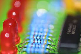
Multicolored LED plate
Is it possible? Yes! But question is that, how? These three different colored diodes (for RED, GREEN, and BLUE) can do this. By adjusting light intensity we can generate 16 million shades by using these three colored LED’s. These LED’s are assembled on the heat sink and several voltage regulators, resistors are connected with them to provide a controlled power supply.
In a simple view we can say a smart bulb contains multicolored LED’s. To know more about LED bulbs click here.
Wireless control circuit:
This circuitry is responsible to provide wireless control to smart bulbs by using Wi-Fi or Bluetooth or both. These controllers have come with some pre-programmed integrated circuits. These pre-programmed IC’s are responsible to make compatibility or pairing smart bulbs with other smart devices like smartphones and also for speech recognition devices like Alexa by Amazon, Google assistant by Google, etc. Here we visit both Wi-Fi and Bluetooth modules for smart bulbs.
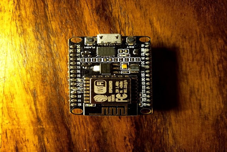
Wi-Fi module in smart bulb
Wi-Fi module:
This Wi-Fi module circuitry gets connected with Wi-Fi enabled devices. In most of the Wi-Fi control board, ‘ESP8266’ Wi-Fi module is being used.
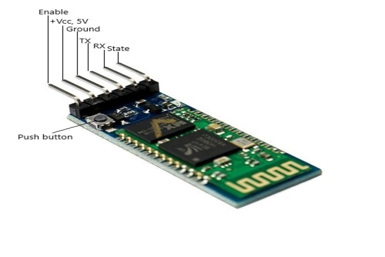
Bluetooth module in smart bulbs
Bluetooth module:
This Bluetooth module creates a paired connection with Bluetooth-enabled devices. HC-05 Bluetooth module commonly used in smart bulbs.
All wireless control circuits are being controlled by their connected or paired devices. And also to provide an interface between these wireless control circuits and your smart device like mobile phones, an application is being used. This application this responsible to sends several commands to pre-programmed wireless controlled circuits to adjust the hue and intensity of light bulbs. Most of the mobile phone manufacturers are providing small applications to perform this task otherwise third-party applications are also available to do the same operation.
Power supply circuit:
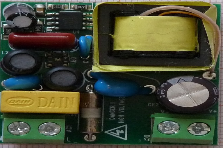
Power supply circuit in smart bulb
It is mainly responsible to provide a power supply to the wireless control circuit and LED bulbs. As we know that LED (Light Emitting Diode) needs DC current for its operation. This circuit is responsible to convert AC current to DC current. LED driver circuit operation is generally different from conventional rectifier circuits.A conventional rectifier circuit step – down the input AC current by using a transformer and after that diodes are used to convert this input into unidirectional or direct current (DC current). But this LED driver makes changes in the frequency of input AC current (220v 50 Hz).
They boost the frequency from 50 Hz to several GHz ranges and after that, it uses several voltage regulators to provide sufficient power to the LED’s and wireless control circuit. Wireless control circuit controlled the output voltage of the LED driver or power supply circuit. This controlled voltage becomes input power to LED bulbs.
How smart bulbs are changing human life:
I don’t need to explain this topic. We have seen it. Smart bulbs are doing better to make human life easy. What about that bulb in your home which can be switch ON or OFF remotely by using IoT (Internet of things). Even you can schedule the timing of your garden lighting. The term smart bulb is self-explanatory to understand its value.
Thanks for reading. See you soon with another exploration!

